
Protection Relay Power Supplies: Selecting Power, Voltage, and Protection
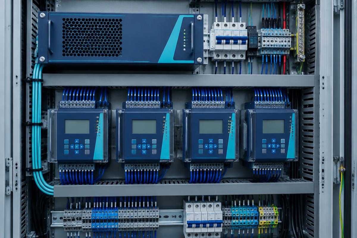
Stable auxiliary power is a prerequisite for dependable protection and control equipment. This guide covers load assessment, input range verification, output protection, and selection considerations for industrial switching and modular rack-mount power supplies.
Power Supplies in the Protection Chain
Protection relays require suitable auxiliary power for measurement processing and output operation. Supply loss can disable an otherwise healthy device. A protection relay power supply must match the relay specifications and auxiliary power architecture. Some relays accept the station DC bus directly and need no external converter.
Establish the Input Conditions
Substations commonly use batteries and chargers to maintain DC control power. A converter may be necessary when bus voltage differs from the equipment requirement. A switching supply alone does not replace a battery, charger, or uninterruptible power system.
Verify the Complete Voltage Range
Battery charging, discharge, and cable losses affect actual input voltage. Confirm minimum and maximum limits, AC or DC compatibility, polarity, and startup behavior. Reverse-polarity protection and surge capability must be documented, not inferred from an industrial product label.
Calculate Load Requirements
List continuous consumption and startup demand for every load. A 24 V DC bus supplying 2 A delivers 48 W. This excludes engineering margin, future additions, and temperature-related derating.
Use manufacturer derating curves rather than an arbitrary capacity percentage. Check overload duration and current-limiting behavior: a supply that supports steady-state demand may fail to start several loads simultaneously.
Coordinate Output Quality and Protection
Ripple, voltage regulation, and transient response must satisfy connected equipment limits. Measure voltage at remote loads under demanding conditions. Raising the output to compensate for cable losses is acceptable only if every load remains within its permitted range.
Electronic current limiting may prevent some downstream breakers from tripping promptly. Coordinate branch protection with the supply characteristics so one faulty load does not collapse the entire control bus.
Installation Checklist
- Maintain specified ventilation clearances and mounting orientation.
- Select cables and input protection for actual operating conditions.
- Separate sensitive wiring from interference sources.
- Measure local temperature under representative load.
Select and Validate the Arrangement
Rizmouj Electric Toos lists protection-relay switching supplies, industrial switching supplies, and modular rack-mount supplies. Modularity does not establish redundancy or hot-swap capability. Parallel operation requires explicit manufacturer approval and suitable coordination.
During acceptance, verify loaded output voltage, simultaneous startup, and recovery after input interruption. Provide input range, output requirements, load profile, ambient temperature, and installation dimensions when requesting a selection.