
Protection Relay Test Blocks: CT Circuit Safety and Proper Panel Testing
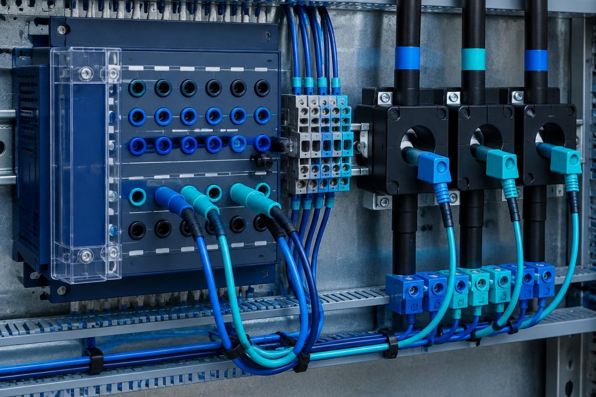
A test block provides controlled access to relay measurement and testing circuits, but safe operation depends on correct design and sequencing. This article explains current and voltage circuit differences, trip-path management, and selection criteria for switch-type test blocks.
Why Use a Protection Relay Test Block?
Relay testing requires access to current, voltage, and sometimes command circuits. Repeatedly removing terminal wiring increases reconnection errors and mechanical wear. A switch-type test block provides defined testing interfaces, but its exact isolation and switching functions depend on the product design.
Distinguish CT and VT Circuits
A conventional current transformer secondary must not be opened while primary current flows. An open circuit can produce hazardous voltage and insulation stress. Establish a secure shorting path on the CT side before disconnecting the relay circuit. Low-power sensors and other measurement technologies require their own manufacturer instructions.
Voltage Circuits Need Different Treatment
A voltage transformer secondary must not be short-circuited. Voltage testing requires suitable isolation and prevention of injected voltage feeding back into operational circuits. Clearly identify current and voltage poles; one switching sequence is not appropriate for every circuit.
Select Against the Circuit Diagram
Define the required current, voltage, common, and command paths. Verify electrical ratings, insulation requirements, terminals, and environmental suitability. Where CT shorting is required, confirm the documented make-before-break sequence for the relevant poles.
Rizmouj Electric Toos lists a switch-type test block. Request its internal diagram, pole arrangement, approved test connections, and operating instructions. Do not assume automatic CT shorting, interlocking, or trip isolation without supporting documentation.
Manage Trip Outputs Before Injection
Secondary injection can operate relay outputs. Decide whether the test covers only the relay or the complete tripping chain. Any trip isolation must follow approved drawings and work authorization. Intertrips and shared logic may require checks beyond a single output contact.
Preparation Checklist
- Use qualified personnel and panel-specific procedures.
- Confirm circuit identity, transformer ratios, and phase assignments.
- Coordinate temporary protection unavailability with operations.
- Inspect test leads and record all temporary isolations.
Define Test Coverage and Restore Service
Secondary injection verifies selected relay functions, not the entire primary measurement chain. An isolated trip output also excludes verification of breaker operation.
Restore circuits using the approved sequence. For conventional CT circuits, establish the normal path before removing temporary shorts. A forgotten short can disable current-based protection. Verify switch positions, command paths, measurements, and alarms, then document authorized return to service.