
Selecting Substation Alarm Annunciators: From Input Count to Alarm Management
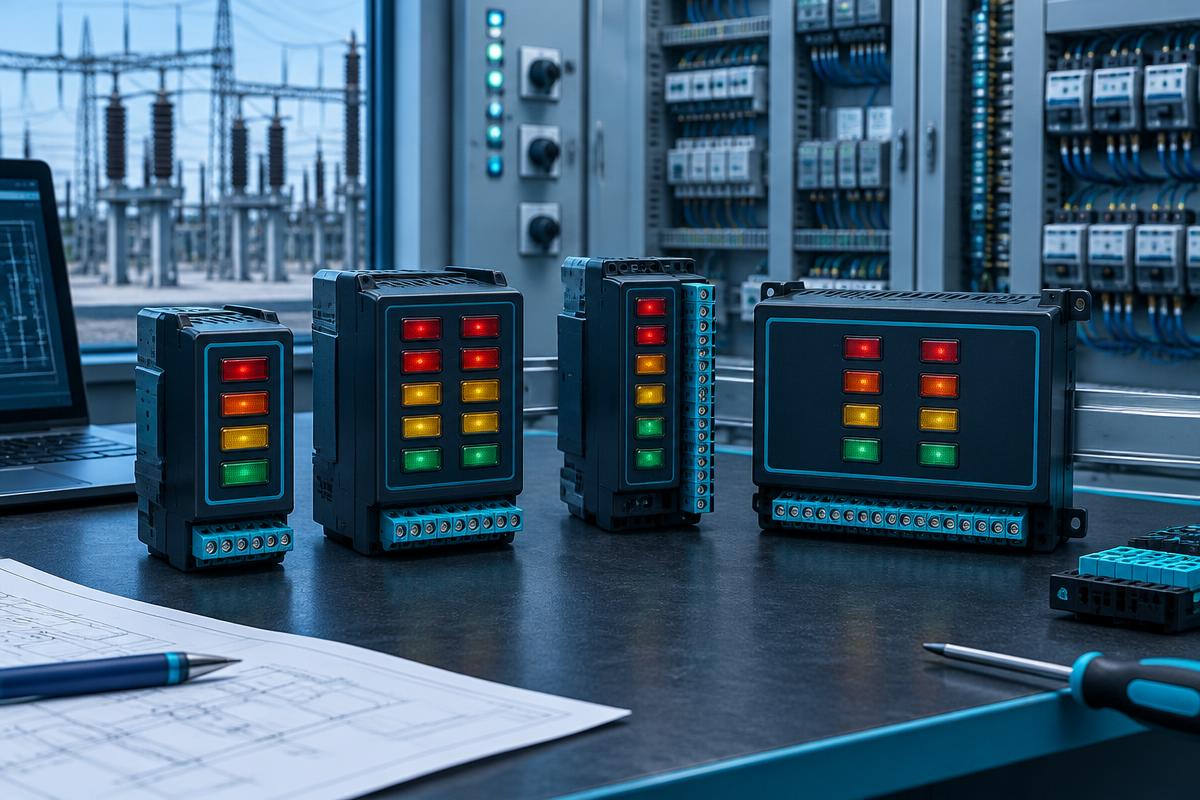
An alarm annunciator turns abnormal equipment conditions into recognizable operator warnings. This article explains selection criteria, input circuit design, and commissioning tests for substations and industrial facilities, while showing how the AMA family can be considered during product selection.
Why Alarm Annunciator Selection Matters
In substations and industrial plants, abnormal conditions must reach operators clearly. Breaker gas pressure alarms, protection operations, charger faults, and transformer temperature warnings require identifiable indications. An alarm annunciator supports operator awareness; it does not replace protection relays or trip circuits.
Define Inputs and Display Requirements
Start with a signal list. Electrical input count, display window count, and individually identifiable events are not necessarily equal. Grouping several faults into one common alarm saves space but reduces diagnostic detail. Reserve capacity should reflect planned expansion.
Considering the AMA Family
Rizmouj Electric Toos lists the AMA520 20-input unit and AMA-535 35-window annunciator, alongside AMA508, AMA510, AMA524, and AMA500 products. Confirm input type, supply range, terminal arrangement, and available functions from the applicable documentation. Model names alone do not establish communication or recording capabilities.
Check Electrical Compatibility
Determine whether each input accepts a dry contact or an externally applied voltage. Applying external voltage to an incompatible contact input can damage equipment. Verify polarity, operating current, common terminal arrangements, and any required isolation.
Check the full auxiliary supply range, including battery charging and discharge conditions. Review power consumption and behavior during supply interruption and restoration. Include internal fault monitoring only when documented for the selected product.
Specify the Alarm Sequence
Alarm arrival, acknowledgment, horn silence, fault clearance, and reset are distinct events. Acknowledgment does not clear the underlying fault. Define whether indications latch after an input returns to normal. Request and verify first-out indication if the application requires it.
Engineering Checklist
- Record each signal name and normal contact state.
- Coordinate contact logic with wiring supervision requirements.
- Separate signal wiring from interference sources.
- Check horn output ratings and use an interposing relay where necessary.
Commissioning and Maintenance
Activate inputs individually and verify labels, lamps, horn operation, and associated outputs. Test simultaneous alarms, acknowledgment, reset, and power recovery. Where delays are adjustable, ensure filtering cannot hide important events. Document expected and observed results.
Inspect indicators, pushbuttons, terminals, and audible warning paths periodically. Coordinate tests with operations personnel. For product inquiries, provide the signal schedule, auxiliary voltage, mounting dimensions, and required alarm sequence rather than selecting by window count alone.